Numerical study on crack thermal resistance effect on thermo-mechanical coupled behavior of concrete structure at room temperature
Cracking behavior in massive concrete structure is inescapable. Cracks would impair the thermal conduction ability of concrete and indirectly induce temperature redistributions, which, in this study, is termed “Crack Thermal Resistance (CTR) effect”. In order to evaluate the influence of CTR on massive concrete structure, a specific thermo-mechanical (TM) coupled model at room temperature, featuring with the evolution of concrete thermal conductivity during material fracture, is proposed based on the thermodynamic principle and concrete damage plastic model. This coupled model is coded as subroutines in ABAQUS and the implementation validated by an uniaxial cyclic test of a single element and a double edge notched specimen (DENS) test. In the DENS numerical test, it is observed that CTR effect can cause heat flux turbulences around cracking area, leading to redistributions of temperature. As a consequence, the stress field and crack opening change around the cracking area as well. In the end, this model is applied to investigate the influence of CTR on the TM coupled behavior of a gravity dam under a long term operation period thermal load. The comparison between the simulations with and without CTR effect demonstrates that (a) CTR effect has a negative effect on structure interior crack propagation, because thermal resistances near dam toe protect the dam from the downstream environment temperature shock; (b) CTR effect can induce redistributions of stress field around the crack area, but the difference in stress field does not affect the compressive stress state on dam-foundation interface.
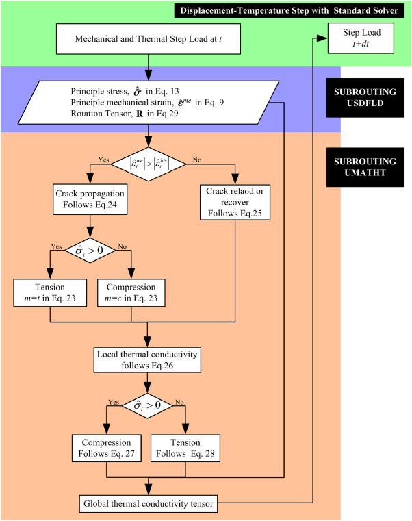
Fig. 1. The flowchart of implementation.
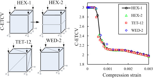
Fig. 2. The influence of mesh size and/or type on the thermal conductivity evolutions. Compression strain unit: -. C-ETCV unit: W/(m · K).
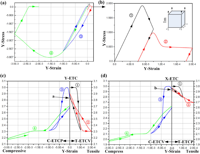
Fig. 3. Results in the cyclic load test. (a) Cyclic mechanical compressive load; (b) Cyclic mechanical tensile load; (c) Y-ETC evolution; (d) X-ETC evolution. Y-Stress unit: Pa. Y-Strain unit: -. Thermal conductivity unit: W/(m · K).
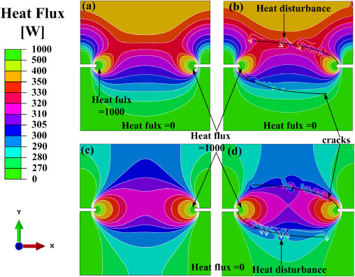
Fig. 4. Heat flux contours of DENS. (a) Case without CTR effect after 2 h of heating; (b) Case with CTR effect after 2 h of heating; (c) Case without CTR effect after 4 h of heating; (d) Case with CTR effect after 4 h of heating.
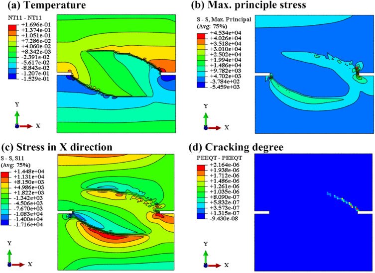
Fig. 5. Difference contours of DENS test (case without CTR effect minus case with CTR effect). (a) Temperature (Unit: ∘C); (b) Maximum principle stress (Unit: Pa); (c) Stress in X direction (Unit: Pa); (d) PEEQT (Unit: -).
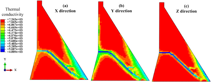
Fig. 6. Thermal conductivity distribution after 50 years. Unit: J/(K · m · month). (a) X direction; (b) Y direction; (b) Z direction.

Fig. 7. Principle stress distribution after 50 years. Unit: Pa. (a) Maximum principle stress; (b) Minimum principle stress.
DOI: 10.1016/j.ijsolstr.2019.07.031