A noise-robust damage indicator for characterizing singularity of mode shapes for incipient delamination identification in CFRP laminates
Identification of delaminations in the early stage is crucial to ensure the safety of CFRP laminates. In the modal domain, high spatial sampling resolution of a mode shape is required for precise location of incipient delamination. Non-contact measurement relying on laser scanning technology allows measured mode shapes to be densely sampled. Unfortunately, noise components usually contaminate such densely-sampled mode shapes, easily causing intense noise interference that likely masks actual delamination features. To address this issue, a noise-robust damage indicator is formulated for designating the presence and location of incipient delamination in CFRP laminates under noisy environments. This damage indicator is created by introducing a 2D multi-resolution modal Teager-Kaiser energy for characterizing delamination-caused singularity of mode shapes. Proof of concept of the damage indicator is numerically undertaken in finite-element CFRP laminates with incipient delaminations, with emphasis on sensitivity to damage as well as robustness against noise. The applicability of the damage indicator is experimentally validated on a CFRP laminate with an incipient delamination, mode shapes of which are precisely acquired via the non-contact measurement using a scanning laser vibrometer. The numerical and experimental results show that the damage indicator can effectively identify the presence and location of incipient delamination in CFRP laminates under noisy environments.

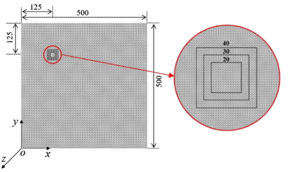
Fig. 2. CFRP laminate with rectangular delaminations (with zoomed-in version) with dimensions in millimeters.

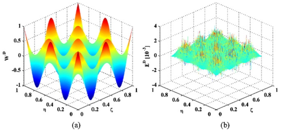
Fig. 3. (a) Measured mode shape and (b) its M-TKE2D for Scenario I.

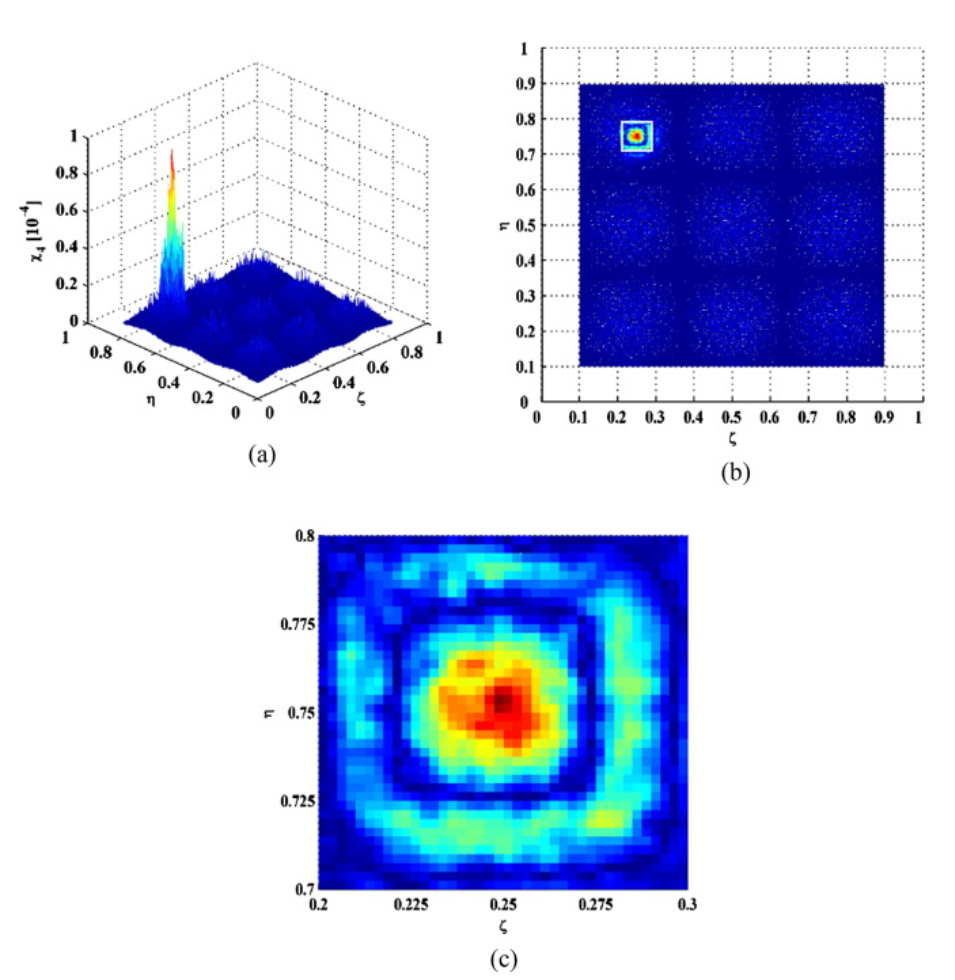
Fig. 5. (a) DI and its (b) planform for Scenario I with delamination outlines marked in white, and (c) zoomed-in version covering delamination region.